
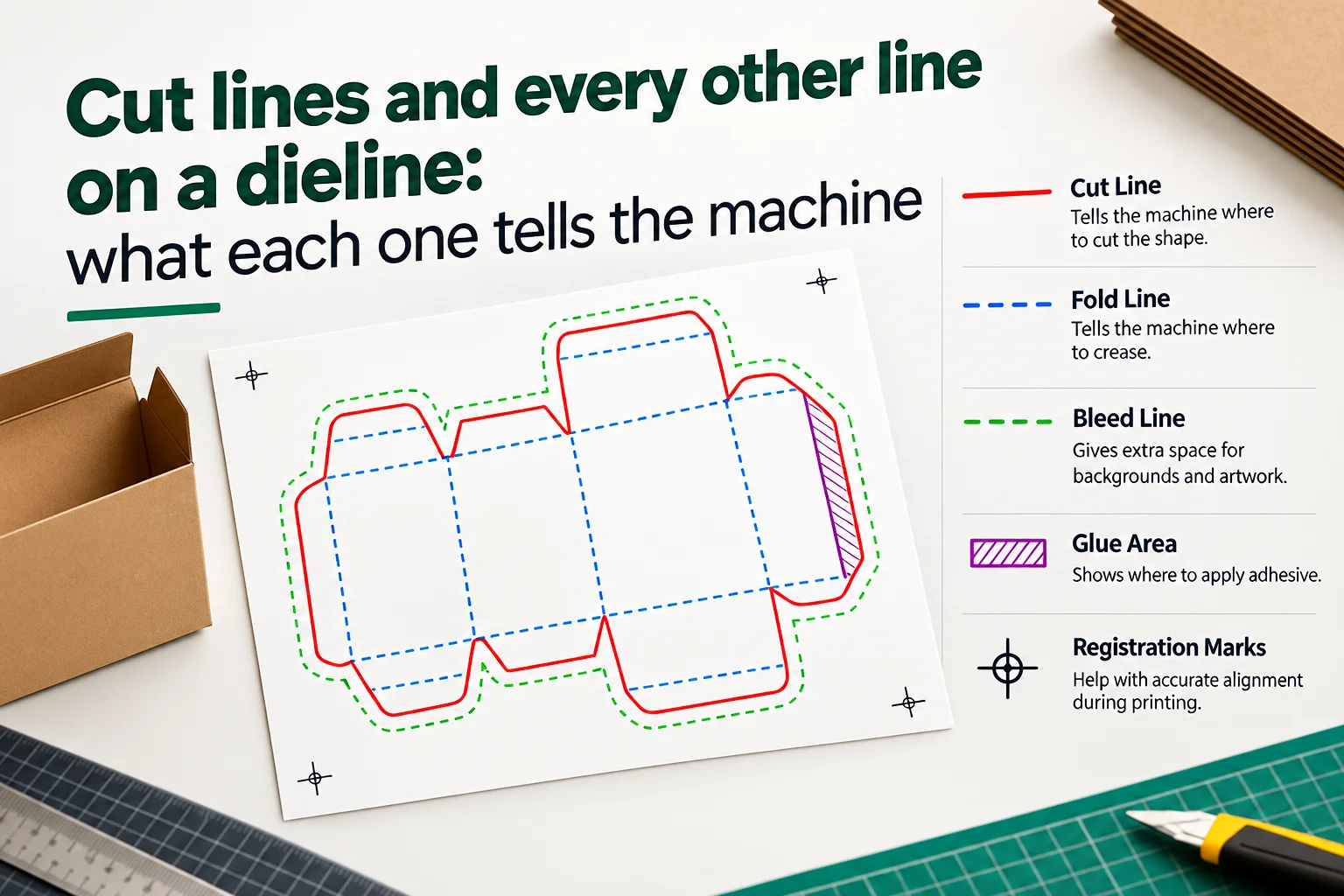
A dieline looks like a single drawing but it is really several drawings stacked on top of each other in one file. Cut lines, crease lines, bleed lines and safety lines all live inside that file, and every one of them speaks to a different machine. The cutting blade goes right through the board. The creasing rule presses a channel so the panel folds where you want it to fold. The printing press lays down the ink. The perforating rule leaves a row of gaps that a customer can tear open with a thumb.
When a shop rejects a dieline, the box itself is almost never drawn wrong. What usually happens is that two of those instructions end up sharing the same line or the same layer or the same color. The converter then has no way to tell which machine each instruction belongs to. That problem takes about five minutes to prevent and about two days to discover once the plates have already been made.
This guide walks through every line you will meet on a packaging dieline. You will see what each one does and where it sits and what goes wrong when it is drawn badly. The table below gives you the short version, and the sections underneath hold the detail you will actually use on a live job.
| Line or area | Common color | What it instructs | Where it sits |
|---|---|---|---|
| Cut line | Red or 100% magenta | The blade cuts right through the board here | The outer outline of the flat |
| Crease or fold line | Blue | The rule presses a channel so the board folds | Every panel and flap boundary |
| Bleed line | Green or cyan | Artwork has to run out this far | 3 mm outside the cut line |
| Safety line | Dashed magenta or cyan | Content stays inside this boundary | 3 mm inside the cut line |
| Perforation line | Dashed red or orange | The rule cuts and skips so the board tears | Tear strips and opening features |
| Trim line | Usually the same as the cut | The sheet gets trimmed here | The edge of the printed sheet |
| Glue area | Hatched or tinted | Adhesive goes down inside this region | Glue flaps and side seams |
Treat those colors as widespread habits rather than as published standards. Your converter might run a completely different set of spot colors and layer names. Never assume that a red line in one supplied file means the same thing in the next one. The layer names matter far more than the colors do because a name survives every conversion the file goes through. The section on layers further down explains how to set them up.
What is a cut line and what does it tell the die maker?
Cut lines carry more weight than anything else in the file because every other element gets measured against them. The cut line draws the physical outline of the blank. It marks the exact path the blade travels when it passes through the board to release the finished shape. Every other element in the file gets positioned against that outline, so the cut line is the one piece of geometry that everything else depends on.
Inside a real die, that line becomes a strip of steel rule with a sharpened edge. The rule sits in a slot cut into a plywood die board and stands proud of the surface by enough height to reach through the material. Rule thickness runs from about 0.45 mm to 1.05 mm depending on the substrate you are cutting. That variation is one reason a drawn dieline and a physical die never agree down to the last hundredth of a millimeter.
Your file has one requirement that matters more than any other. The cut line has to be a single closed path with nothing hidden underneath it. Duplicate cut lines show up constantly in files that were copied between documents, and die making software reads that duplicate as a second knife. You will not see it on screen during a normal review, but you will see it later as extra tooling complexity and a higher die price.
How do you check that a cut path is really closed?
A path can look perfectly closed on screen while its two endpoints sit a fraction of a millimeter apart. Illustrator will still draw the shape without complaining, and the gap only surfaces when prepress or die making software reports an open contour.
The quickest test takes about ten seconds. Select the shape and drop a solid fill into it. A properly closed path fills evenly across the whole flat. An open path either refuses the fill or spills it somewhere obvious, and either result tells you exactly where to look. The Document Info panel gives you the same answer in a more formal way if you prefer to read it as numbers.
Why does the cut line not always match the finished edge?
On corrugated board the finished edge drifts slightly away from the drawn geometry because the flutes and the liner compress as the knife passes through them. The drift stays small on thin folding carton stock and grows on heavier corrugated grades. It matters most when you are working to a tight dimensional tolerance or fitting a carton around a product with very little clearance.
This is why any dieline generator gives you a mathematical description of a structure rather than a promise about the physical result. Tooling, material thickness and converting tolerance all move the finished carton away from the drawing by a small amount. Build a little clearance into the structure and the drift stops being something you have to manage. A carton that fits its product with half a millimeter to spare will survive the normal spread of production tolerance.
What is a crease line and how does it differ from a cut?
A crease line tells the machine where the board has to bend. A creasing rule never cuts through the material because its working edge is rounded instead of sharpened. It presses the board down into a matrix channel on the far side of the sheet and leaves a compressed hinge behind.
That hinge is what lets a carton fold in the same place again and again without cracking along the fold. The matrix channel has to be wider than the board is thick, so material caliper feeds directly into the geometry of the crease. Board thickness is not a production footnote here. It is an input to the drawing.
Why does board caliper change where a crease sits?
A crease has real width in the physical world even though you draw it as a line with no thickness at all. The board has to travel around the outside of the fold, and thicker board needs more room to make that journey. Miss that allowance and the carton either refuses to close or bulges visibly at the corner. The error grows with every fold the structure contains, so a tuck end box shows it far more clearly than a tray does.
Take a structure drawn for 0.5 mm folding carton stock and run it on 1.5 mm E-flute corrugated board without changing anything. The flat stays identical while the material triples in thickness, so the finished box loses internal volume and stops fitting the product it was designed around. The panels have to grow to absorb the extra caliper.
Treat caliper as geometry rather than as a note on the job bag. When the material changes, panel dimensions and crease positions have to change with it.
When do you need a reverse crease?
Most folds run in the direction the die and matrix set up for you. Some structures need a panel to fold the other way, and that fold needs the creasing setup flipped to the opposite face of the board. A crease pressed from the wrong side will crack along the outer fiber instead of hinging cleanly.
Hinged lids use reverse creases constantly. So do several mailer structures where one panel folds back against its neighbors. If your structure contains a reverse fold, label it in the file and repeat it in the production notes. Geometry alone will not communicate fold direction reliably.
Are fold lines and crease lines the same thing?
In everyday packaging language a fold line and a crease line describe the same place on the board. The difference sits in who is speaking rather than in what the line does.
Designers reach for the phrase fold line because they are describing what the finished carton does once it reaches the customer. Converters reach for crease line because they are describing the operation that puts the hinge there in the first place. Both people are pointing at the same geometry.
The word score is the one that genuinely shifts meaning. On corrugated board a score sometimes means a partial cut that helps a thick grade bend without bursting. When a converter asks you for a scored line, ask them which operation they mean before you change anything in the file.
Where is bleed measured from on a dieline?
Bleed is artwork that runs past the cut line so no white edge appears when the print and the die fail to line up perfectly. Every press has registration tolerance, and bleed is the allowance that absorbs it.
Three millimeters is the common figure across folding carton work. Your printer might ask for more on a particular substrate or a particular converting route, so treat 3 mm as the default rather than as a rule. The number matters less than where you measure it from.
Bleed gets measured outward from the cut line. It does not get measured from the nearest panel boundary and it does not get measured from a crease. Those two lines sit on top of each other across the main panels of a straight tuck end carton, which is exactly why the mistake goes unnoticed. Around dust flaps the crease and the cut separate, and artwork measured from the crease leaves the real cut edge short.
What happens when there is not enough bleed?
The press and the die cutter drift against each other by a small amount on every single sheet. A well run job holds that drift inside a few tenths of a millimeter. It never reaches zero.
When the artwork stops short of where the knife lands, that drift opens a thin white stripe along one edge of the finished carton. The stripe moves from sheet to sheet because the drift moves, so one pallet shows it on the front panel and the next shows it on the side. Customers notice it immediately even though it measures less than half a millimeter.
The frustrating part is that your proof looks perfect. A proof shows the artwork sitting exactly where you drew it because no physical tolerance exists inside a PDF. The tolerance only arrives when the job reaches a press.
Can a file carry too much bleed?
Too much bleed does far less damage than too little, so err upward when you are unsure. The one place it causes real trouble is a gang run sheet where several different cartons share the same press form.
Artwork that extends 10 mm past its own cut path will wander into the neighboring carton on a tightly nested sheet. Keep to 3 mm for ordinary work and tell your converter whenever a job needs more than that. They lay out the form, so they need to know before they nest it.
How far inside the cut line does your content need to sit?
The safety line marks the boundary your important content stays inside. It goes by several names including the safe zone and the keep away area, and it is the only line in the file that no machine ever reads.
Text and logos and barcodes and legal copy all belong inside that boundary. Three millimeters inside the cut line covers most folding carton work. Small cartons and awkward panel shapes need more, because the same physical tolerance eats a larger share of a small panel than it does of a large one.
Creases deserve as much respect as cuts here. Type that crosses a fold survives the die but becomes hard to read once the board is bent. Photography distorts across a crease. A barcode laid across a fold gives scanners real trouble even when every bar survives intact. Keep the safety boundary on a locked guide layer while you work so it stays visible on screen and never prints by accident.
Why do barcodes need more room than text?
A barcode carries its own margin requirement called the quiet zone. The scanner uses that clear space to find where the symbol starts and stops, so the quiet zone is part of the barcode rather than decoration around it. Its width depends on the symbology and on the magnification you print at.
Work out the quiet zone from the barcode specification first and then check that the whole symbol still clears your safety line. The two margins are separate requirements and the larger one wins. Keep barcodes off creases and off curved corrugated panels wherever the structure gives you a flat alternative.
What does a perforation line tell the die?
A perforation rule cuts and skips in a repeating pattern instead of running a continuous knife through the board. The cut sections release the material and the uncut sections hold the carton together until somebody tears it.
Perforation patterns get written as a ratio of cut length to tie length. A 3:1 perforation cuts for three millimeters and leaves one millimeter of board intact, which tears very easily. A 1:3 perforation reverses that and holds on hard. Choosing between them is a judgment about the journey the box takes.
A pattern that tears too easily will open inside a shipper during transit. A pattern that holds too well turns the unboxing into a wrestling match and sends the customer looking for scissors. Ask your converter which ratios they already hold rules for. Using a pattern they own costs you nothing at all, while a custom ratio adds tooling time and money to the first order.
How do tear strips work?
A tear strip runs two parallel perforations with a narrow band of board between them. Pulling the band lifts it away and splits the carton along a path you chose in advance.
Strip width decides whether the feature works. A strip under 6 mm gives fingers almost nothing to grip. A strip over about 15 mm stops tearing along the perforations and starts ripping through the middle of the board instead. Somewhere between those two numbers is where the feature feels deliberate.
How does board grain change the tear?
Paperboard has a grain direction and it tears far more willingly along the grain than across it. The same perforation pattern therefore behaves differently depending on which way you orient the structure on the sheet.
When a tear feature is central to how the product opens, agree the grain direction with your converter before the die gets made. Grain is set by how the sheet runs through the press, so it is a layout decision rather than something you fix afterward.
What is a trim line and when does a dieline need one?
A trim line marks where the printed sheet or the roll gets cut down. It describes the boundary of the printed area rather than the shape of the carton, so it belongs to the sheet instead of to the box.
Conventional sheet fed work with a cutting die often needs no trim line at all, because the die releases the carton and nothing else has to be trimmed. Digital and roll fed routes are different. There the trim boundary becomes part of the production file and the converter reads it directly. Ask which route your job is taking before you decide whether the file needs a trim boundary at all.
Trim tolerance and die cutting tolerance are two different numbers and they rarely match. A guillotine works to a tighter figure than a cutting die does, so the two processes pull your margins in opposite directions. When one file carries both, set your safety margins against whichever process has the looser tolerance. Working to the tighter one leaves you exposed on the other.
Why are glue areas drawn as regions instead of lines?
A glue area covers a patch of board rather than following a path, so it gets drawn as a hatched or tinted region. It tells the gluer where adhesive lands and it tells you where artwork has to stay out of the way.
Adhesive needs raw board or a coating it can key into. Flood varnish and lamination and heavy ink coverage all interfere with that bond in different ways. A glue flap buried under full coverage varnish will hold on the line and let go three weeks later in a warehouse.
Many converters knock the coating out of the glue area automatically during prepress. Drawing the region yourself removes the guesswork anyway, and it costs you about a minute. Mark the region yourself and nobody downstream has to make that decision on your behalf. The gluer knows where the adhesive lands and prepress knows exactly which coating to knock out.
How should colors and layers be set up?
A dieline file has one job beyond geometry. It has to make the purpose of every element obvious to somebody who has never seen your artwork before.
Color carries part of that message. Magenta or red for cuts and blue for creases and green or cyan for bleed are widespread conventions. None of them is a published standard, which means color alone will never be enough.
Layers carry the rest, and they carry more of it than color does. A file with layers named Cut and Crease and Perforation and Bleed and Safety and Artwork explains itself regardless of which colors anybody uses. A file with everything sitting on Layer 1 forces the converter to reverse engineer your intent from the swatch panel. That takes them time you are paying for and it introduces a guess that nobody needs.
Which mistakes get a dieline sent back?
| What went wrong | What the shop sees | How you avoid it |
|---|---|---|
| Everything sits on one layer | Instructions have to be read from color alone | Split the file into named layers before you send it |
| The cut path is duplicated | Two knives where the die needs one | Delete hidden and stacked copies of the outline |
| The dieline is merged into the artwork | Geometry that nobody can isolate | Keep the dieline on a layer of its own |
| Lines have been outlined | Filled shapes instead of technical paths | Leave technical lines as strokes |
| The dieline layer is set to print | Cut and fold marks printed on the finished box | Set it to non printing or use the approved spot color |
That last row catches more people than the other four combined. A dieline left as ordinary printing artwork comes back as a carton with cut and crease marks printed across the panels. Nothing in the file warns you beforehand, so the first sign of trouble arrives on a pallet.
How do you read a dieline somebody else drew?
Most of the dielines that reach you will have been drawn by somebody else. Before you touch the artwork you need to work out how that person chose to communicate.
Open the Layers panel first and read the names. Named layers tell you a professional built the file and that its structure is worth trusting. A single layer called Layer 1 tells you to slow down and check everything yourself.
Isolate the cut layer next and look at the flat on its own. It should read as one recognizable structure without stray paths hanging off it. Anything you cannot explain is either a second carton ganged onto the same sheet or a fragment that somebody left behind during an earlier edit. Both are worth resolving before you build artwork on top of them.
Turn the creases back on after that and walk the panel boundaries. Files that were traced rather than generated lose creases regularly, and a missing crease turns into a panel that refuses to fold in production.
Finish by measuring one dimension you can check against the brief. Take the front panel width between crease centers and compare it to the number you were given. When those two disagree, stop and ask, because everything downstream sits on that measurement. Structure codes help here too. The FEFCO code names corrugated styles and the ECMA code names folding carton styles. A file labeled with either one tells you what shape to expect before you measure anything.
How do you measure a dieline with no dimensions on it?
Plenty of supplied files carry no dimensions whatsoever. Measuring them yourself is the only way to find out what you have been sent.
Measure between crease centers rather than between the visible edges of the crease. A physical crease has width, so the center is the only point you will land on the same way twice.
Regenerating the structure is faster still when the shape is a standard one. Most supplied dielines are, and there are dieline templates for box structures you can measure against. Build the same structure at the stated dimensions and lay the two flats over each other. Any difference between them jumps out immediately.
What should you check before you send the file?
A dieline preflight takes about ten minutes on a file you have never seen. Almost every item below is faster to check now than to fix after the plates exist. Run through the list before the file leaves your machine. Ten minutes spent here is the cheapest insurance available on a packaging job.
- Every line type sits on its own layer and the layer names say what they are.
- The cut path is closed and it appears exactly once with nothing stacked underneath.
- Bleed runs 3 mm outward from the cut line unless your converter asked for a different figure.
- Bleed is measured from the cut path itself and not from a crease, including around every flap.
- Important content sits at least 3 mm inside the cut line and nothing critical crosses a fold.
- Barcodes have their quiet zone and they sit on a flat panel rather than across a crease.
- Glue areas are clear of varnish and lamination and heavy ink coverage.
- The dieline layer is set to non printing or to the spot color your converter asked for.
- At least one dimension has been measured between crease centers and checked against the brief.
- Reverse creases and special scores and perforation ratios are all labeled in the file.
Getting the geometry right before you start on artwork removes the first five items from that list, and those five cause most of the rework. You can generate a packaging dieline for your own structure at your dimensions and your board caliper. The export gives you a flat with the cut and crease and bleed already sitting on separate layers.
The lines on a dieline are not decoration and they are not a house style. Every one of them is an instruction aimed at a specific machine, and the file works when each machine finds its own instruction without having to guess. A good dieline is not a box that looks right on screen. It is a set of instructions that travels from your desk to the factory floor without anybody having to ask you what you meant.
← All posts